PCB Pin Header Selection Guide
What Is a PCB Pin Header?
A PCB pin header is a common board-level connector made of one or more rows of conductive metal pins held in an insulating plastic housing. It is used to create a detachable electrical connection between a printed circuit board (PCB) and another circuit, module, or connector. In component datasheets and connector catalogs, a pin header is often described as a product with “molded metal pins in an insulating housing” that can carry signal, power, or data.
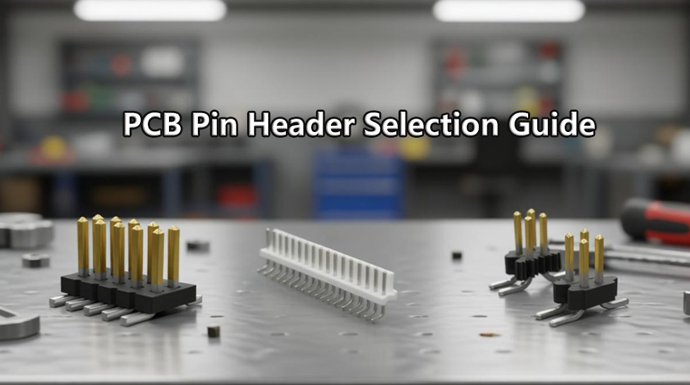
Compared with a permanent soldered connection, a PCB pin header offers more flexibility and is widely used in modular designs, development board expansion, embedded systems, and prototype debugging. For example, in Arduino or Raspberry Pi projects, pin headers make it easy to connect sensor modules or expansion boards without complex wiring.
Core Definition and Procurement Notes
| Item | Content |
| Term | PCB pin header |
| Product category | PCB connector / board-level connector |
| Common names | pin header, PCB header, male header, header pins |
| Mating parts | female header, socket, receptacle, jumper wires, IDC cable |
| Typical applications | board-to-board connection, wire-to-board connection, module interface, prototyping |
| Key purchasing parameters | pitch, rows, positions, mounting type, datasheet |
In real sourcing work, searching only for "PCB pin header" is not enough. Engineers and buyers need to define the critical parameters, such as 2.54 mm pitch, single-row or dual-row, through-hole or SMD, and then confirm dimensions, electrical performance, and material specifications in the datasheet.
● Pin header vs PCB header
"PCB header" is a broader term that refers to connector types mounted on a PCB, while "pin header" is one specific form, usually referring to a connector with exposed metal pins.
In everyday conversation, these terms are often used interchangeably. But in datasheets, selection, and procurement, "pin header" is more specific and typically ties directly to pitch, pin count, and pin arrangement. That level of precision is important for BOM management and alternative part evaluation.
● Male header, female socket, and receptacle
Structurally, a PCB pin header is usually the male side, meaning the side with exposed pins. Its mating connectors include the following:
- Male header: Usually soldered to a PCB or used as the plug side, featuring exposed metal pins fixed in a plastic housing. Common pitches include 2.54 mm, 2.00 mm, and 1.27 mm.
- Female socket / female header: Contains spring contacts or sockets that receive the male pins. It can be an SMT or through-hole PCB-mounted type, or a wire-side socket, and is used to create a detachable connection.
- Receptacle: A more formal term often used in datasheets or interconnect standards to describe the female side that accepts male pins. In some contexts, it may overlap with "socket," though in power or panel applications it often refers to a fixed outlet-style connector.
Together, these connectors form a complete interconnect system. During design, the mating parts must match mechanically, such as pitch and mating height, and electrically, such as current and voltage rating. Otherwise, the design may suffer from poor contact or long-term reliability issues.
Application and Function Summary
The core value of a PCB pin header is that it enables a detachable connection. Typical functions include:
- Signal transmission: Used for GPIO, communication interfaces such as UART, SPI, and I2C.
- Power distribution: Supplies power to a module or daughterboard.
- Data connection: Supports data transfer in modular systems.
- Prototyping: Works with breadboards or jumper wires for fast circuit building.
- Board stacking: Used in expansion boards and daughterboard structures.
Because of its simple structure, low cost, and broad compatibility, the pin header has become one of the most fundamental and widely used connection solutions in electronics.
Buying and Selection Reminder
Before choosing a specific MPN, it is best to confirm the following parameters first:
- Pitch, such as 2.54 mm, 2.00 mm, or 1.27 mm.
- Row count, such as single row or dual row.
- Pin count (positions).
- Mounting type, such as through-hole or SMT.
- Pin length and plating, such as gold finish thickness.
Once the specifications are confirmed, you can search by MPN through an electronic components distributor like UnikeyIC to view datasheets, compare specifications, confirm stock status, or request a quote. That helps improve sourcing efficiency and reduce selection risk.
Main Types of PCB Pin Headers
A PCB pin header is not a single specification. It is a family of board-level connectors. In engineering selection and procurement, you normally need to evaluate it by orientation, row count, position count, shrouding, mounting style, and mating interface. Looking only at the term "pin header" is rarely enough to complete an accurate selection.
In datasheets and distributor catalogs, you will often see terms like straight, right-angle, stacking, single-row, dual-row, through-hole, SMT, and press-fit. These describe different selection fields, not the same classification layer. Understanding that distinction helps you lock down the MPN faster, reduce alternative-part mistakes, and make stock checking and quoting more efficient.
● Straight, right-angle, and stacking headers
The most common classification starts with orientation. A straight header is a vertical pin header with pins extending perpendicular to the PCB. It is commonly used when the mating socket, cable interface, or module connects from above the board.
A right-angle header is a 90-degree pin header with pins extending along the PCB plane. It is useful when enclosure height is limited, when cables need to exit sideways, or when the connector must avoid top-side interference.
A stacking header is mainly used for board-to-board stacking, often found in expansion boards, daughterboards, and mezzanine structures. Its focus is not simply "connecting wires," but controlling the height, spacing, and mating stability between two PCBs.
● Single-row, dual-row, shrouded, and unshrouded headers
The second classification is row count and housing style. A single-row header has one row of pins and is commonly used for low-pin-count signal breakout, debug ports, or simple interfaces. A dual-row header has two rows and is common in development boards, industrial control boards, and higher-density signal connections. Higher pin-count versions may also use multi-row layouts.
From a housing perspective, a shrouded header includes a plastic guide wall or shroud that improves alignment and reduces mis-mating risk. An unshrouded header is an exposed pin structure that is more compact and commonly used in basic headers and cost-sensitive designs. Another common variation is a breakaway header, which can be cut to length and is often used in prototyping, lab boards, and general-purpose inventory.
● Through-hole, SMT, and press-fit options
The third classification is mounting style. A through-hole header is soldered into plated holes on the PCB and provides strong mechanical retention, making it a good fit for prototypes, industrial control boards, and applications that need higher insertion and extraction force.
An SMT header is suitable for automated assembly and compact layouts, but whether it supports reflow soldering must be verified in the datasheet. Do not assume all SMT headers are reflow-ready unless the documentation clearly states reflow support, package orientation, and temperature limits. A press-fit header relies on press-fit pins to create a mechanical and electrical connection in the PCB hole. It requires tighter control of hole tolerances, board materials, and plated-hole quality, so it should not be treated as a universal soldering alternative.
Pin Header Type Identification Matrix
| Header |
type |
What to verify Datasheet file |
Procurement note |
| Straight | Orientation, row count, positions | Drawing, pin length, tail length | Confirm MPN before stock check |
| Right-angle | Board exit direction, clearance | Drawing, footprint, tail length | Watch enclosure and cable routing |
| Stacking | Board height, mating spacing | Standoff height, drawing | Verify board-to-board compatibility |
| Shrouded | Shroud, alignment, anti-mis-mating | Housing drawing, mating interface | Good for guided mating |
| Unshrouded | Exposed pins, pitch, positions | Pin layout, footprint | Common in basic headers |
| Through-hole | Hole size, tail length, solder side | PCB footprint, pin tail | Watch hole tolerance and retention |
| SMT | Pad layout, coplanarity, reflow fit | Footprint, package type | Do not assume all parts support reflow |
| Press-fit | Hole spec, compliant pin structure | Drawing, press-fit dimensions | Verify plating and board thickness |
This table helps you quickly identify what to check when you see a part number. For buyers and engineers, type fields should be confirmed before alternative-part evaluation or ordering.
What to confirm first when sourcing?
If your goal is to check stock, compare specs, or send an RFQ, start by locking down the orientation, row count, position count, mounting type, and mating socket. Once those fields are clear, you can browse related products and compare specifications more effectively, and avoid adding mechanically incompatible parts to the BOM.
In actual work, many selection mistakes do not come from pitch errors. They come from choosing the wrong orientation, row count, or mating part. A safer engineering workflow is to confirm the structure first, then review pitch, current rating, plating, and mechanical life. That also makes it easier to compare parts across brands.
Key Specifications to Check Before Selection
Although a PCB pin header looks simple, its actual suitability and reliability depend on the specific parameters listed in the datasheet. For engineers and buyers, the right approach is not to ask whether a "pin header" is available, but to first confirm pitch, positions, rows, orientation, and mounting type, then verify current rating, contact plating, insulator material, and operating temperature.
Once the type is identified, you move into the actual specification selection stage. In other words, the previous sections answered "what is it" and "what types are available," while this section answers "how do I choose the right one."
● Pitch, positions, rows, and pin length
The first specification to confirm is pitch. The most common PCB pin header pitch is 2.54 mm, but that is not the only standard. For compact or high-density designs, 2.00 mm and 1.27 mm versions are also common. Different pitch values require different mating female headers, sockets, receptacles, or IDC cable interfaces, so similar-looking parts are not automatically interchangeable.
Next, check the number of positions and the row count. Single-row, dual-row, and multi-row headers differ significantly in PCB footprint, board-edge space, mechanical alignment, and mating part selection. Many sourcing problems happen because the buyer looks at "10 pins" but ignores whether that means 1x10, 2x5, or another arrangement.
Pin length and tail length also need to be verified together. They affect insertion depth, solder-joint strength, board height, and mating reliability. For stacking headers, right-angle headers, or board-to-board applications, these dimensions are especially important because they directly define the spacing between two PCBs.
● Electrical ratings and contact plating
PCB pin header electrical specifications usually include current rating, voltage rating, and contact resistance, along with contact material and contact plating for long-term reliability. One common mistake is to assume that the same pitch means the same current capability. In reality, current rating depends not only on spacing, but also on pin geometry, contact area, plating, and product design.
Common plating options include gold plating and tin plating. Gold plating is often preferred when low contact resistance, higher mating reliability, and longer mating-cycle life are important. Tin plating is more common in cost-sensitive and general-purpose applications. The right choice depends on mating frequency, environment, and service life, and should always be verified in the datasheet.
Insulator material and operating temperature should also be reviewed. The housing material affects heat resistance, mechanical stability, and solder-process compatibility. The operating temperature range determines whether the part is suitable for industrial, automotive, or high-temperature applications. If compliance documents are required, also check RoHS, REACH, or other certifications.
● Datasheet fields buyers should verify
A good datasheet should be treated like a sourcing checklist, not just a product page. This table is useful during specification comparison, sample review, and BOM creation.
| Field |
What to verify |
| MPN | Exact part number |
| Manufacturer / brand | Brand and series match |
| Pitch | 2.54 mm, 2.00 mm, 1.27 mm, or other defined pitch |
| Number of positions | Total pin count |
| Number of rows | Single-row, dual-row, or multi-row |
| Row spacing | Distance between rows |
| Orientation | Straight, right-angle, stacking, etc. |
| Mounting type | Through-hole, SMT, press-fit |
| Pin length / tail length | Mating depth and solder tail length |
| Current rating | Meets the actual application current |
| Voltage rating | Meets the application voltage |
| Contact plating | Gold, tin, or other finish |
| Insulator material | Material and heat rating |
| Operating temperature | Covers the intended environment |
| Packaging | Bulk, tube, tray, tape and reel |
| Compliance documents | RoHS, REACH, and similar docs |
| Mating connector or socket | Matching female header, socket, or IDC interface |
This checklist helps bring a "looks similar" part back to measurable engineering parameters. Many alternative-part failures do not come from brand differences. They happen because row count, pin length, mounting style, or mating part was not verified.
Practical selection order
A safer workflow is to first lock down pitch, positions, rows, orientation, and mounting type, then verify electrical and material details. That makes it easier to check stock, screen alternative parts, and send RFQs.
If you are handling procurement, the best next step is to compare specifications, confirm the datasheet details, check current stock, and then prepare the RFQ or BOM line item on UnikeyIC. On a distribution platform, checking specifications first and stock second is far more efficient than doing it in reverse.
Mounting and Assembly Considerations
For a PCB pin header, mounting method matters just as much as pitch, row count, and pin count. In real engineering and procurement work, the assembly method affects whether the part fits your PCB design, production process, packaging format, and sourcing strategy. Mounting is not just "how it gets installed"; it also affects footprint, board thickness, packaging, rework difficulty, and compatibility with existing SMT or through-hole processes.
Once the core specifications are confirmed, this section narrows the question to whether the header is suitable for through-hole, SMT, press-fit, or through-hole reflow / pin-in-paste. Getting this right makes RFQs, BOMs, and sample validation much smoother.
● Through-hole, SMT, and press-fit selection
A through-hole header is the most common plug-in style. It is best suited for traditional soldering processes. For sourcing, the key points are hole size, tail length, PCB thickness, and compatibility with wave soldering, selective soldering, or hand soldering. This style usually provides stronger mechanical retention and is a good fit for applications that need higher insertion force, field service, or prototype use.
An SMT header is better suited for automated assembly and compact designs. Selection requires confirmation of pad footprint, coplanarity, packaging, and pick-and-place compatibility. Do not assume every SMT header is automatically reflow-compatible. If the datasheet does not clearly state that it supports the required assembly conditions, you should not assume compatibility.
A press-fit header relies on a compliant pin to create a mechanical and electrical connection in the PCB hole. It depends more heavily on PCB hole requirements, tooling considerations, and hole quality. That makes it more sensitive to board materials, tolerances, and plated-hole quality. It is a good fit for projects with defined tooling and stable production, but not for casual substitution.
If the design uses through-hole reflow or pin-in-paste, then high-temperature material compatibility becomes critical. In that case, you must verify the thermal behavior and the assembly drawing rather than assuming that a part with the same appearance will work.
Mounting Method Selection Notes
| Mounting method |
PCB footprint requirement |
Assembly process impact |
Packaging to confirm |
Datasheet field to verify |
RFQ note |
| Through-hole | Hole size, tail length, board thickness | Suitable for wave / selective / hand soldering | Bulk, tube, tray | Hole dimensions, pin tail, assembly drawing | State soldering process in RFQ |
| SMT | Pad size, coplanarity | Suitable for pick-and-place and reflow | Tape and reel, tray | Footprint, package, reflow rating | Confirm SMT compatibility |
| Press-fit | PCB hole quality, press-fit engagement | Cold press assembly, tooling dependent | Tray, bulk | Compliant pin spec, hole requirements | Verify hole tolerance and tooling |
| Through-hole reflow / pin-in-paste | High-temp material compatibility | Reflow-dependent process | Tray, tube, bulk | Material and thermal rating | Confirm process window before buying |
This table makes it easy to see how different mounting methods affect procurement and assembly. In many cases, the component itself is not the problem. The issue is packaging, process compatibility, or a PCB footprint mismatch.
● Soldering questions that belong in a separate guide
Some questions look related to installation but actually belong in a separate assembly tutorial. For example: How do I properly solder a PCB pin header to a circuit board? How do I solder wires to headers? Should I shorten these pin headers before soldering to the PCB? Those topics are better handled in a separate soldering or assembly guide.
RFQ sourcing note
In real purchasing, it is best to include both the mounting method and the assembly process in the RFQ instead of just writing "pin header." That helps sales and engineering teams identify the correct available part, packaging format, and process fit.
If you are building a BOM or sending an RFQ through UnikeyIC, the safest approach is to first confirm the datasheet and assembly drawing, then verify current stock and packaging options such as tape and reel, tray, tube, or bulk. Clearly stating these details upfront makes spec comparison, alternative-part screening, and availability checks much more efficient.
Sourcing PCB Pin Headers for BOMs and RFQs
Once PCB pin headers move into production sourcing, the question is no longer "what is it," but how to turn a broad category term into a MPN-based sourcing information that is ready for ordering, price comparison, and alternative evaluation. For BOM sourcing and RFQs, a generic keyword is only useful for initial research. Production sourcing usually requires an exact MPN, manufacturer, datasheet, pitch, positions, rows, orientation, mounting type, and quantity.
In other words, the earlier sections covered selection, while this section covers procurement execution. If the specifications are not locked down, stock checks, lead-time discussions, alternative-part reviews, and pricing conversations become much less efficient.
● Search by MPN, not only by generic keywords
For formal procurement, avoid relying only on generic searches like "PCB pin header." Instead, use the Manufacturer Part Number (MPN). The reason is simple: parts that look very similar may still differ in brand, series, pitch, pin length, plating, or other details, and may not be interchangeable.
The first fields to confirm should include:
- Manufacturer / brand
- Exact MPN
- Datasheet
- Pitch
- Positions
- Rows
- Orientation
- Mounting type
If you already have a target part number, the most efficient workflow is to search by MPN first, then verify the datasheet, mating connector, and dimensional details. That helps you quickly confirm whether the part is the one you need and avoids treating a similar-looking part as an acceptable substitute.
● Check stock, price breaks, MOQ, SPQ, and lead time
When you move into quoting, you should look at current stock, unit price, volume pricing, MOQ, SPQ, and lead time. These factors directly affect BOM cost, delivery timing, and whether a part is practical for bulk purchase.
When evaluating availability, pay attention to the following:
- Stock availability: Whether the part is in stock and whether the available quantity is sufficient.
- Unit price / volume pricing: Whether the unit cost and price breaks fit the procurement target.
- MOQ / SPQ: Whether the minimum order quantity and standard packaging quantity fit the sample, pilot, or production schedule.
- Lead time: Whether the delivery schedule affects validation or launch timing.
- Package / mounting type: Whether the packaging format is suitable for SMT, through-hole, or manual assembly.
Do not assume fixed price, fixed MOQ, or fixed lead time. Those items vary by part number, order quantity, and market conditions. A safer way to phrase it is to first check current stock, then contact sales to confirm availability, pricing, and packaging options.
● Compare equivalent or alternative headers carefully
Alternative-part evaluation is one of the easiest places to make mistakes. Many buyers assume that if the pitch matches and the row count matches, the part is interchangeable. In practice, that is not enough. You need to know which parameters can change and which cannot.
The following fields are usually not safe to change casually:
- Pitch
- Row spacing
- Pin length / tail length
- Contact plating
- Current rating
- Mounting footprint
- Orientation
- Mating connector requirement
If these fields differ, the part should not automatically be treated as an equivalent substitute, even if it looks similar. For production programs, also verify electrical specifications, operating temperature, compliance requirements, quality control, and genuine component checks. The point is not just to find stock. It is to make sure the substitute will not affect assembly, reliability, or final performance.
RFQ Preparation Module
Before sending an RFQ, it helps to organize the following information in advance. That makes it easier for suppliers to quote quickly and reduces back-and-forth.
| Field |
What to confirm |
| Target MPN | Exact part number |
| Manufacturer / brand | Brand and series |
| Pitch | Required spacing |
| Positions | Number of pins / circuits |
| Rows | Single-row or dual-row |
| Orientation | Straight, right-angle, stacking |
| Mounting type | Through-hole, SMT, press-fit |
| Contact plating | Gold, tin, or specified finish |
| Quantity | Required order amount |
| MOQ / SPQ sensitivity | Packaging and purchasing constraints |
| Target lead time | Sample or production schedule |
| Compliance requirement | RoHS, REACH, or other documents |
| Mating connector required | Yes / no |
| Alternatives accepted | Yes / no |
| BOM line notes | Special handling or approval notes |
This table helps turn "I need a pin header" into a complete sourcing item. For distribution purchasing, the more complete the information is, the easier it is to determine availability, substitutes, packaging fit, and whether the quote fits the project timeline.
FAQ for PCB Pin Header Buyers
PCB pin headers may look simple, but in purchasing and selection, the key is to clearly explain the definition, types, specifications, and sourcing logic. The FAQ below covers the questions buyers ask most often.
● Quick Buyer Questions
Q1: What is a pin header?
A pin header is a board-level connector made of one or more rows of metal pins held in an insulating base. It is commonly used to connect a PCB to a female header, socket, receptacle, ribbon cable, or another circuit board. In sourcing, always confirm pitch, positions, rows, and mounting type.
Q2: What is a PCB header?
PCB header is a broader term for connectors mounted on a PCB. A pin header is one common form, usually referring to a connector with exposed male pins. In real selection work, the term "PCB header" does not mean all similar products are interchangeable. MPN and datasheet verification still matter.
Q3: What are the different types of PCB pin headers available?
Common types include straight, right-angle, stacking, single-row, dual-row, shrouded, unshrouded, through-hole, SMT, and press-fit. Each type fits different board space, mating direction, and assembly method requirements. Start with PCB layout, mating connector, and assembly process before choosing one.
Q4: What are the standard sizes and pitch measurements for PCB pin headers?
One of the most common pitches is 2.54 mm, but 2.00 mm and 1.27 mm are also widely used, especially for compact designs. In addition to pitch, confirm positions, rows, row spacing, pin length, and tail length. Two headers that look similar may still not mate or interchange correctly.
Q5: Is a pin header suitable for high current?
Only if the datasheet current rating clearly supports the application. Current capability depends not only on pitch, but also on contact design, plating, pin geometry, and temperature conditions. During procurement, always verify the rated current first instead of assuming a header can handle high current just because it fits.
Q6: How should I source PCB pin headers for a BOM?
The safest method is to use the exact MPN, then verify the manufacturer, datasheet, stock availability, and packaging. If alternative parts are acceptable, confirm which fields can change and which cannot, such as pitch, row spacing, pin length, plating, and mounting footprint. After that, prepare the RFQ or BOM item.
● Questions better split into soldering or troubleshooting guides
Questions such as How do I properly solder a PCB pin header to a circuit board?, How do I solder wires to headers?, Should I shorten these pin headers before soldering to the PCB?, and What are the best practices for troubleshooting loose connections in PCB pin headers? are soldering, assembly, or troubleshooting topics. They are better covered in separate articles.